- Is That a Game on My Phone?
- The Pipeline for Making Mobile Games
- Exercise 7: Creating Assets for a Mobile Robot Shooter
- Creating Levels
- Making Props, Pickups, and Other Stuff Lying Around
- Exercise 8: Creating Prop Designs and Textures
- Creating a Crate Texture Map
- Creating FX for the Mobile Space
- Exercise 9: Creating a 2D Sprite-Based Effect
- Chapter 4 Wrap-Up
This chapter is from the book
This chapter is from the book
This chapter is from the book
Creating Levels
In the beginning, there were robots, and the designer saw these robots and said, “Now where can they fight swarms of aliens for somewhere between one to two minutes?”
Creating levels is a job that takes a village. Many things have to come together to make a level work correctly, and if you plan on churning out hundreds of levels that only last a minute or two each, you’d better make sure that everyone knows what they are doing from the start. If not, you will be redoing a lot of stuff in your future.
What is this stuff, you ask? Well, it all starts with—guess what—an idea that is usually handed down from the designer, or in a larger studio, a writer who hands it off to the designer. In your sample game world, the designer and the art director hired a concept company to flesh out some images to be used as examples or inspiration for levels. The look of the level you need to create is shown in FIGURE 4.21.
)
FIGURE 4.21 Spaceport city.
The designer’s instruction to the concept house for this image was:
Create a spaceport with ships coming and going, and cargo stacked around. It should be industrial, and have a dirty modern feel to it. This is the first level of the game.
The concept house did its job, and it is enough for you to start laying out some of the groundwork that will turn into this level.
The first thing you need to do is identify all of the elements that need to be in the level to make it work. These might be a road, or a special rock, or a bridge the player has to cross. Your level design must include anything that is a critical part of the gameplay.
You can get this list from the designer, who has thought this through. Even so, it is also a good idea to sit down with the designer and have her walk you through her design process (FIGURE 4.22). This is the kind of meeting that dry erase boards were invented for.
)
FIGURE 4.22 Doodles on the whiteboard.
Here are the mission-critical items that the designer wanted addressed. Keep in mind these might change, but you need to start somewhere.
- Square buildings
- Spaceport landing pads
- Sidewalks
- Square landing pad
- Spaceships
- Flag objects
- Streetlights
- A floor is implied
- A height elevation drawing showing how tall the robots can be
At this point, you should be able to draw a rough layout. It has a beginning, an end, and a variety of stuff in the middle.
Creating a Basic Level Map
The level map is created in multiple sections that can be recolored and moved around as the level is dialed in. The sections are the ground plane, the road, the buildings, and all the movable objects such as crates and trees. When you are done, you will have a pretty good idea of what the level will look like from a top-down view. By conceiving the level in this way, you can make changes before time is spent in 3D modeling.
A good way to start is to take a picture of the whiteboard and the work you did with the designer. You can then bring that right into Photoshop and draw on top of it, after some careful cropping and stretching. Keep in mind that this is just the rough sketch, not the final. The map could change quite a bit before you are done.
Creating the Navmesh
The first step is creating the ground that your characters will walk upon.
- Once you have your image ready to go, create a new file in Photoshop. Name it LV1_Spaceport, and make it 20 inches wide by 5 inches high at 300 dpi. In the filename, LV stands for level, and you add “1” to indicate the first level, followed by a description of what is in that level.
- From the rough map file, which you should have open, select the layer that has the rough map on it, and drag it into your new LV1_Spaceport file. Save the file.
Create a new layer and call it Navmesh ( FIGURE 4.23). This word is an abbreviation of navigation mesh, and it will be the ground on which the hero and the bad guys will travel. By constraining the characters’ movements to a particular piece of geometry, you ensure that they will not clip (penetrate) through larger pieces of the world. You also only have to create the physics code once, and then just apply it to the path. That way any new characters you add will follow the rules of the code you set as long as they are walking on the path. Also, physics code is expensive to run so you do not want it applied to the whole world, especially to the places you can’t go.
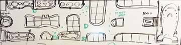
FIGURE 4.23 Navmesh sketch.
Set the navmesh layer Opacity to 60%. Using the Pen tool, choose a red color ( FIGURE 4.24). Trace the outline of the floor area as best you can. Do not worry about the details too much, you will clean it up later. In fact, the fewer points you can use, the better.
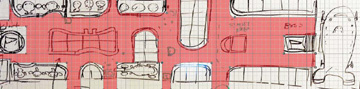
FIGURE 4.24 Highlight areas of possible travel.
- Now choose View > Show > Grid to turn on the grid. This will help you clean up your lines.
Choose the Direct Selection tool, a few tools down from the Pen tool. Try to align the points with the nearest grid point, so when your 3D modeling begins, the shapes can be built with a minimal number of polygons ( FIGURE 4.25). Everything you do at this point should be geared to saving polys.
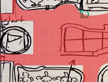
FIGURE 4.25 Create a vector image to get right angles in your mesh.
When you get your shape to a respectable state, you can create a new layer just below the navmesh layer, and merge the shape down. Make sure that you raise the layer opacity before you do so. This merge will convert the navmesh from a vector shape to a raster image. You did not ultimately want this shape as a vector shape, but it is easier to align it in that state. You could do this whole part with the Brush tool, if you wanted, but you would need a very steady hand.
With the shape now editable in raster mode, you can clean up any stray lines and make any cutout corrections you might require. This navmesh will be used as a template to make the polygon mesh ( FIGURE 4.26). For now, you will not apply any colors.

FIGURE 4.26 Vectored navmesh.
)
)
Creating the ground plane
Creating the ground plane is very easy because it is, very simply, the size of the whole file. In this case, it’s 6000x1500 pixels at 300 dpi. The ground plane is the very bottom of the stack, which means it is the most obscured of the elements. This is great because in 3D, the ground plane usually receives a tiled texture, which is a 2D image that is applied to the polygon multiple times to make the ground plane look like a single image. It is usually a lot smaller than 6000x1500, more like 512x512. The repeating texture then fills in the 6000x1500 area. 512? Why this odd number? It’s all about the Power of Two rule.
You are going to create a 512x512 texture tile that will be applied to the ground plane. It will be a tiling texture that looks like it is not repeating, especially when you are suggesting grass or dirt (FIGURE 4.27). For this reason, natural tiles are generally harder to make. Second, a tiling texture must be able to be located next to another tile on any of the four sides of the square, without the seam showing.
)
FIGURE 4.27 Ground textures.
Because this level is a spaceport, you will be making a metal grid tile.
Begin by creating a file that is 1024x1024 at 72 dpi. (Most final images going into an engine are at 72 dpi.) You will reduce this to 512x512 later, but if you need a higher-resolution version in the future, you will have it. Fill it with a dark gray color (FIGURE 4.28).

FIGURE 4.28 Create a metal tile for the outer frame.
- Choose Image > Canvas Size, and set it to 1050x1050, which will create a perfect stroke space around the outside edge. Fill the new empty space with a lighter gray. Choose Image > Size, and change the size back to 1024x1024.
- Using the Magic Wand tool, select the inner square and cut it from the file. Then choose Edit > Paste Special > Past in Place. Name the lower layer trim, and the upper layer base.
Select the trim layer, and in the blending options, select Bevel & Emboss and Gradient Overlay (FIGURE 4.29). Set the Depth to 113 and the Size to 8.
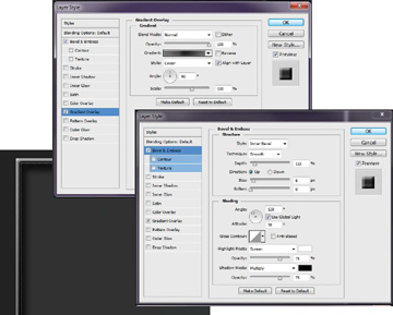
FIGURE 4.29 Blending options.
Using the Shape tool, pick an industrial-looking pattern from the shape gallery. In this example, the multiple diagonal line shape was used (FIGURE 4.30). Position the pattern in the middle of the square so there is a small border. In the blending options, select Bevel & Emboss and Drop Shadow. Make sure Bevel & Emboss is set to Pillow Emboss, and that the Depth is set to 164 (FIGURE 4.31).
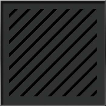
FIGURE 4.30 Place the shape from the gallery.
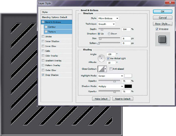
FIGURE 4.31 Adjust the blending options.
Create a new layer called emblem. Using the Ellipse tool, create a circle in the middle of the page (FIGURE 4.32). Fill it with the base color, and once again select Bevel & Emboss and Drop Shadow.
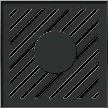
FIGURE 4.32 Add a circle shape.
From the Custom Shape tool library, select a shape that will work as an emblem, such as the atomic shape. Center it in the circle, and open the blending options. Select Bevel & Emboss and Drop Shadow. Make sure the Style is set to Emboss and the Direction is set to Down (FIGURE 4.33). Save your file.
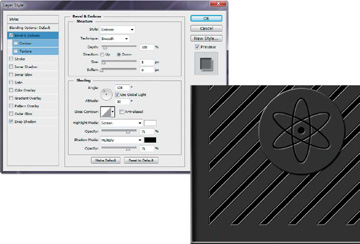
FIGURE 4.33 Add a custom shape and adjust the blending options.
Create another layer called dirt. Select one of the scatter brushes, such as number 24, and then select black as your fill color. Dot the pattern around the layer, changing the size and position (FIGURE 4.34).
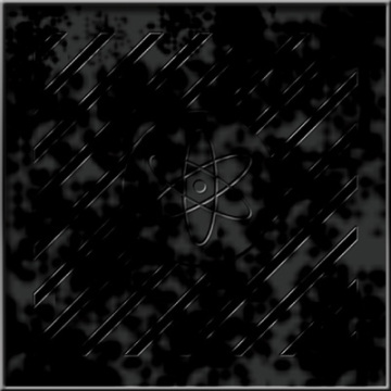
FIGURE 4.34 Begin creating a “dirt” layer.
Create a new layer and call it dirt2. Select an orange color, and switch to a different scatter brush (FIGURE 4.35). Repeat the painting process, but do not paint as much of the area as you did previously.
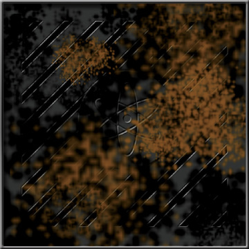
FIGURE 4.35 Add color to the dirt layer.
Create a new layer, and call it dirt3. Using a blue color and a new scatter brush, once again apply small doses of paint, and add more shapes to the mix (FIGURE 4.36).
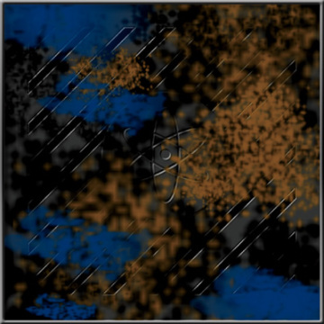
FIGURE 4.36 Add more color and shapes to the dirt layer.
- Adjust the opacity of the three layers until you are satisfied with the look. When you are satisfied, merge the three layers together, return to the diagonal shape layer, and select the inside of the grooves using the Magic Wand. Then on the dirt layer, erase the dirt in the grooves but not the dirt on the emblem section.
- If you feel the need, you can add another dirt map. In the example, the shadows were accentuated a bit with a layer inserted under the emblem layer.
Now it is time to test your tile. Save the file as a TIFF or PSD. Collapse all the layers and save it as a PNG. Choose Image > Canvas Size, and change the file size to 2048x2048. Locate your image in the upper-left corner. Duplicate the layer three times and move each layer to a corner of the square (FIGURE 4.37). Check for obvious mistakes and verify the tile blends with other tiles.
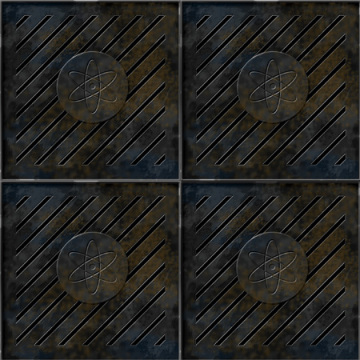
FIGURE 4.37 Duplicate the tile and position one in each corner.
When a tile like this is used in a game, a shader and lighting are often applied. So even if the lighting in the drawing is not perfect, the engine will bring it together. That being said, it is a good idea to do the best you can with the illustration because the game engine can do only so much to make a tile work.
FIGURE 4.38 shows what the tile looks like rendered in 3ds Max with simple lighting and an object added to show what a shadow looks like on the tile. The tile in the image is set to repeat five times over the surface of the ground plane. A simple shader has also been added.
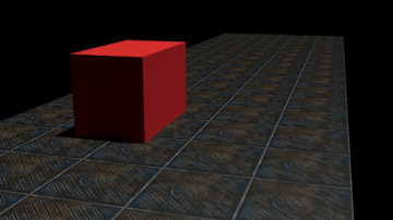
FIGURE 4.38 The tiles applied to a ground plane.
- Now that you know the ground plane will work, you can apply it to your level map. Save a PNG version of your tile that has only one tile. You may need to crop it to fit. Make sure it is 1024x1024.
Open your level map file again and import the tile image. Tile the image across the entire ground plane without going beyond the borders (FIGURE 4.39). This is best done by placing the tile down, and then selecting and duplicating the two tiles. Then select the four new tile layers and duplicate them.

FIGURE 4.39 The navmesh on top of the ground plane.
- When you have the area filled, collapse all the layers together into one layer called ground tile, and scale it the little extra bit to fit the area. You just need an idea of how it works; you have the tile for the actual game asset.
)
)
)
)
)
)
)
)
Creating Stand-in Buildings
Designing a building is a bit of a trip down architecture lane. Just as in real architecture, the design must fit into your environment. You can’t have a Victorian house at your spaceport; it just won’t do. So you need to design a building that will look right for the location. It should have all the trappings of a spaceport café, or storage unit, or customs office. Think space station meets shipping yard. Actually, any of those would be fine, but because the concept illustration had a café in it, that is where you will start.
Because you are only making a level map, you have no real need to flesh out a fully realized building design. Players will see it only from the top. But in the interest of learning, you will flesh out an isometric view of the café, and then generate a top-down view based on that design.
You can go about designing a structure for a 3D environment in two ways. One is to just design the building as best you can, and then let the 3D modeler figure out how to bring it in within the polygon budget. The other is to design the building with the poly budget in mind, making sure that everything you place on the page has been considered from a modeling point of view. You are going to use the second method.
Begin by opening up the diametric grid file you used on the robots. Scale the grid down in height by 50% to get a more front-on perspective. Make sure your file is 6 inches high by 10 inches wide at 300 dpi (FIGURE 4.40).
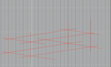
FIGURE 4.40 Create the volume box for the first part of the building.
- Using the Line tool with a red color at 4 pts, begin to lay out the foundation of your space café. It will be three polygonal shapes: the main floor, the smaller second story, and the roof sign. It has purposefully been kept simple to keep the poly count low. But this means that you’ll have to do quite a bit with texture.
- Once you have the main floor in place, create a new layer called 2ndstory, and repeat what you did with the first layer, except leave a bit of a border. When you are dealing with low poly models, any surface area that you can create to reflect light is a good one.
When you have finished the 2ndstory layer, create a new layer called roof sign. Using the Line tool, finish creating the layout for the shape (FIGURE 4.41). It will look a little like a bunch of crazy toothpicks. Do not worry.
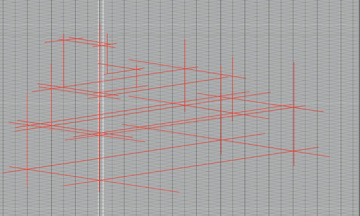
FIGURE 4.41 Create the volume box for the second part of the building.
Select the Line tool and choose a black color, and keep the size at 4 pts. Create a new layer called blackline, and begin to outline your shape (FIGURE 4.42). If it helps, you can reduce the opacity of the red line layers just a bit.
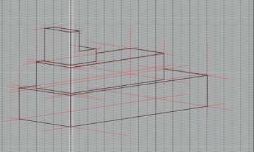
FIGURE 4.42 Begin creating the building.
With the main structure in place, you can start working on the decorations, which include windows, doors, vents, signs, and pipes. In 3D, most of these will just become part of the texture, but that would depend on how many polys you’ve spent in other places. However, these elements always look better in 3D if you actually build them.
Begin with the doors (FIGURE 4.43). They are good to nail down because they give the structure a sense of scale. Your average industrial external door is about 7 feet high by 34 inches wide. Space café doors are just a little bit larger than that. Don’t worry too much about fully fleshing out the doors right now. Just use the grid to indicate where they are. If you really can’t help yourself, you can indicate a door jamb.
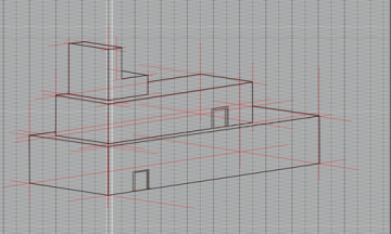
FIGURE 4.43 Flesh out the doors.
With the doors in place, the next logical element is the windows (FIGURE 4.44). Windows in a space café differ from those in a real diner. Instead of being big and open, they are small, more akin to what you would see on a boat or an airplane. Smaller windows will help sell the idea that the environment is in space. Notice that the windows were also given a bit of dimension.
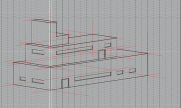
FIGURE 4.44 Create the windows.
Now you will add some things that look terribly important, but are really there just to fill some of the empty space. Repetition on a building is very common. In fact, you almost expect it. So let’s not disappoint.
Just above the lower door, use the Pen tool to create a trapezoidal shape similar in size to the door ( FIGURE 4.45). Make sure the bottom line is on a horizontal grid line and that the outer edges also line up with vertical grid lines. You will need these markers in the next step. The look you are going for is a protruding piece of geometry.
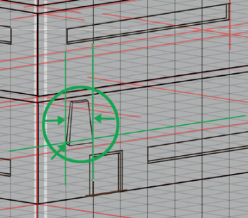
FIGURE 4.45 Create the first part of the wall decoration.
Now collapse any shapes to a single layer, and call it decoration. Duplicate the decoration layer and slide it 2 grid spaces over to the right. Repeat this until you run out of building (FIGURE 4.46). Collect all the layers into a layer group, and name it decorations lower.
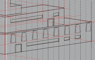
FIGURE 4.46 Duplicate the decoration layer.
In the remaining empty spaces on the café, continue to create visual distraction or interest, depending on your view of life. In FIGURE 4.47, you can see the space for signage, a large tank of some sort, and a ventilation unit. All of the things a space café cannot do without.
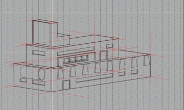
FIGURE 4.47 Continue to create visual interest by adding details.
Create a new layer and call it sidewalk. Choose the Line tool and create a 1-unit sidewalk around the base of the building (FIGURE 4.48). This will help sell the scale of the building and give you a place later on to put things such as lights and space café vending machines.
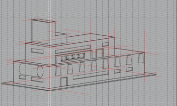
FIGURE 4.48 Create a 1-unit sidewalk.
Collect all of the layers and duplicate them. Collapse the new layers into a single layer, and name it color. Fill in the shapes you have created using gray tones. You can also use tonal ramps if you want. Color the windows in green (FIGURE 4.49).
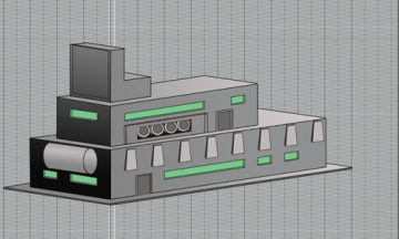
FIGURE 4.49 The finished space café with colors applied.
)
)
)
)
)
)
)
)
)
)
You should have produced more than enough for the 3D artist to start work, and far more than you need for your level map. If you were concepting this, you would also apply colors and finished details such as the signage and perhaps stuff in the windows. You would also do a reverse angle if it were needed.
Creating real stand-in buildings
Creating the building markers for a real level map is far easier than what you just did. The kind of building you actually need to make has the footprint of the building and callouts for any doors, windows, or turrets that might be important. No grids, no shading, very simple. The building images are generally done as in an architectural drawing: a large whitish area with a few hash marks and an indication of which way the door swings (FIGURE 4.50). If the building is accessible, you might need some indication of the inside layout, but usually that is a separate map with more detail.
)
FIGURE 4.50 Create the level layout tags.
- Open the level map file you were using. With the Shape tool, create a rectangle that fits the area in the middle. Fill the shape with a white-gray color and make the Stroke blue. With the Text tool, write SPACE CAFÉ. Collapse the layers into a single layer called space café.
Repeat this for all the sections, giving each a name based on what you and the designer discussed. Because these items may change at any time, make sure that they are all on their own layers.
Most studios have a visual shorthand for calling out repeated items without spelling out the actual name again and again. This accounts for the yellow dots with the red borders and the little pictures of bombs. They stand for a destructible object in this case; that is, an object that can be shot and has the potential for causing damage to bad guys or other players. You might also see shorthand symbols for things like lights, spawning points, save points, and various other common game objects.
To make the destructible object icon, choose the Ellipse tool and draw a small circle. Make the fill yellow and the border red. Create a new layer above that layer, and with the Brush tool, create a little image of a bomb. Merge the two layers together, and name the new layer destructible object.
This map is now more or less ready to take to the designer. She will place notations on a new layer to indicate where spawn points may be and what special purposes the various buildings might have, if any. After that, the map is distributed to the team as a guide for what is needed to flesh out the level. A list of assets will be created, and engineering will document the tasks that might be needed for this particular scenario to explain the functionality. The main point of a map like this is to get everyone synchronized on the objectives rather than waste time and energy spinning in the wrong direction.
Creating a Texture Atlas for the Navmesh
Remember that tile you made for the ground plane? You’re going to take it a step further. A texture atlas is a group of textures that are all on one sheet, and then applied to one or more objects repeatedly in a game engine to give a more diverse, less tiled look. The reason for putting them on one sheet is that they load faster as a slightly larger file than they would as five little files. You’re going to make a series of tiles, collect them on an atlas, and then apply them to the navmesh.
First, you need to identify the types of tiles you will need for the navmesh object. You do this by looking at the layer in Photoshop and seeing how it turns and bends, while trying to come up with some options that will work in multiple locations.
- Open the level map file. Hide everything but the red navmesh layer.
- Create a new layer. Identify similar shapes in the path that could use a single tile once or multiple times. With the Brush tool, mark these in rough outline using a black color. Identify as many sections as you need.
Number each similarly shaped area.
As you can see in FIGURE 4.51, you have identified four map types. Each of these tiles will need to look as if they are made from the same material, but they do not all need to tile from every direction as did the previous tile.
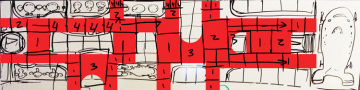
FIGURE 4.51 Number each similarly shaped area.
Now you will break each of the numbered areas out into individual maps. Remember that each map needs to fit into a power of two square, which is 512x512.
Open a new file in Photoshop that is 1024x1024 at 72 dpi. Name it navmesh_t1. As you can see, this is a larger area tile, which means that the detail will have to be smaller.
“Why is that?” you ask. Let me explain. The tiles you make will start out the same on the tile atlas, but when applied to the sections of the object in a 3D software package, they may end up displaying at different sizes (FIGURE 4.52). So, if you have details like the black border and the 33 in this image, they must start out at different sizes in the 512 maps so that when reduced they are the same scale.
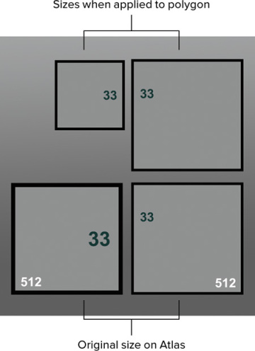
FIGURE 4.52 Tiles may end up displaying at different sizes.
Notice how large the black trim and the 33 have to be in the original tile to appear to be the same size in the model. It is important that you identify these situations in advance, or you will get way down the road with your project and then have to redo your work.
Create a new file that is 1024 inches in height and 4540 inches in width at 72 dpi. Select an example of each of the tile shapes, and import them into the new file, placed next to each other. You do not need to add the numbers here.
Once you have the pieces, you can begin work on filling them in with space station road-looking art. A good way to start is to create a stroke around each of the shapes (FIGURE 4.53). Because these will look like metal floor tiles in the game, a border is a great natural break. It will look like the edge of the tile. If you were drawing dirt, it would be much harder to hide the seams of the tile.
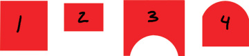
FIGURE 4.53 Lay out your shapes next to each other.
Fill the shapes with a gray-green color (FIGURE 4.54). This is a popular space-station floor color. In the blending options, turn on Bevel & Emboss, and set the Depth to 360. Then create a new layer and call it background. Move it to the bottom of the stack, and fill it with a gray color. Once again, this is done so you can see what you are doing.
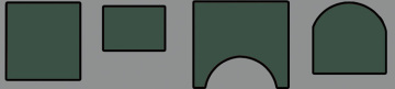
FIGURE 4.54 Fill the shapes with a gray-green color.
Select all the green areas, and copy and paste them. This will create a new layer that you can name lid. Name the original layer base. In the blending option of the lid layer, turn on Drop Shadow and Bevel & Emboss. Marquee select the first shape in the lid layer, and center it over its base layer counterpart (FIGURE 4.55). Repeat this for all the shapes. Note that the third arch shape will also need to be scaled a bit to fit.
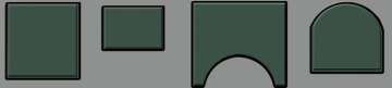
FIGURE 4.55 In the blending option of the lid layer, turn on Drop Shadow and Bevel & Emboss.
From here you can add a central theme to each tile (FIGURE 4.56). You have gone with a grate theme because this spaceport has a lot of rain, and drainage is important. Oh, and you added one tile one for visual variety.
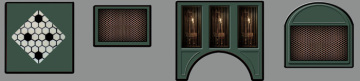
FIGURE 4.56 Add a central theme to each tile.
After your central theme is in place, you can create a new layer above the others and call it dirt map1. You’re going to be adding some years to your tiles, just as you did with the ground plane tiles (FIGURE 4.57).
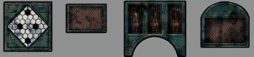
FIGURE 4.57 Add some colored dirt to the tiles.
- Select a black color and a scatter brush, just as you did before, to create some interesting shapes. If you go too heavy with the paint, you can lower the opacity, or select the Eraser tool and a different brush and work back the other way. When you are happy with the mess you have made, create another map, and using a color (such as blue), add some colored dirt.
- Duplicate all the layers and, with the exception of the gray background, merge the new ones together. Hide the old layers.
- Create a new file that is 1024x1024 at 72 dpi, and name it texture atlas. This will be your texture atlas, as the name suggests. You will stack your files in a square so they will be made easier to read by the game engine.
Create a red, square shape that is 512x512. Place it in the upper-left corner, and duplicate it to the lower-right corner (FIGURE 4.58). Collapse the layers. These squares will be used to size your texture maps to 512x512.
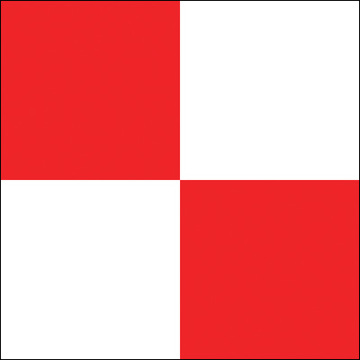
FIGURE 4.58 Create a red, square shape that is 512x512.
Marquee select tile number 1, and paste it within the upper-left red square. Scale the image until it covers most, if not all, of the red square. As you can see in FIGURE 4.59, you have now made your texture 512x512.
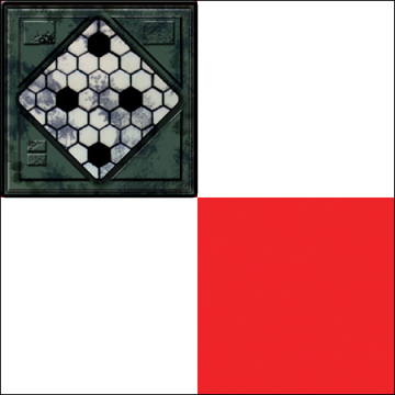
FIGURE 4.59 Marquee select tile number 1.
Repeat this process for the remaining tiles, stretching them to fit the entire space (FIGURE 4.60). Don’t worry; you will squish them back to their normal sizes later.
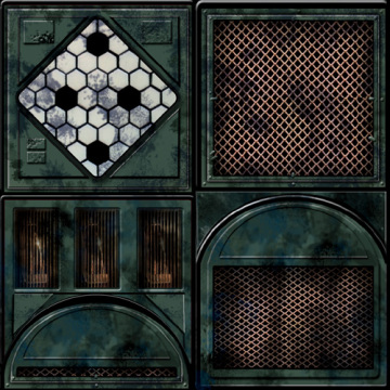
FIGURE 4.60 Repeat the selection/paste tile process for the remaining tiles.
Create a layer above the red-checkered level and fill it with a black color. Save the file as a TIFF and a PNG. Obviously, some space on this atlas has not been utilized. Space on a texture atlas is never wasted, and usually you would put a texture for something else into these areas. For now, you will leave it blank, but you should make a mental note that you have some space for a small texture if you need it.
With your texture atlas, you will now simulate how it would be applied to a mesh object in a 3D software package such as Autodesk Maya or 3ds Max.
)
)
)
)
)
)
)
)
)
)
Applying the Texture Atlas to the Navmesh
Without the aid of 3D software, applying a texture to a mesh is a bit difficult, to say the least, but you can simulate the process using Photoshop layers and some creative pasting.
In a 3D world, a 2D image is projected onto the surface of a 3D object. The projection can be cut into small sections based on the 3D topology. Each polygon can have its own 2D map, but most of the time the process goes more like this: One 2D image is carefully positioned over multiple polys on an object to give the illusion of it having color, being painted, or wearing pants or dragon scales, or whatever (FIGURE 4.61). That is exactly what you’re going to do with your navmesh.
)
FIGURE 4.61 Apply 2D maps to each polygon.
- Open the navmesh file you’ve been using with Level map master.tiff, and hide all the layers except for the red navmesh layer.
- Also open the texture atlas.png file, and copy the whole file.
- Return to the navmesh layer, and use the marquee tool to select the red area.
Choose Edit > Paste Special > Paste Into. You should now have a version of the texture atlas floating around in the red area. Move the texture atlas layer to the area you identified as a number 1 zone. Move and scale the atlas in area 1 to fit the space (FIGURE 4.62). Don’t worry about spillover from the rest of the atlas because you will cover it up soon.
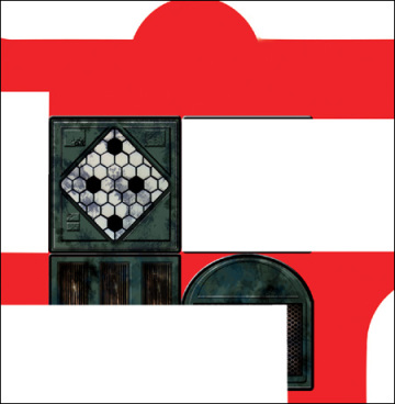
FIGURE 4.62 Move and scale the atlas in area 1 to fit the space.
What you’re trying to do here is use the four images on the atlas to fill out portions of the red area. Generally, you would do this without any nonlinear scaling because the stretching is an obvious tell that a texture is being applied.
Repeat this technique until the entire red area is filled (FIGURE 4.63). Refer to the number map you created earlier, if you need to. Do not worry about strictly adhering to the number map, as it was more of a guide than anything else. Try to introduce variation into the pattern if you can.
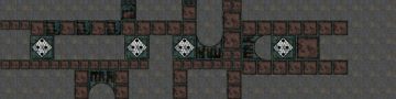
FIGURE 4.63 Fill the entire red area.
A top-down view of the ground map never looks as good as a perspective view. If you were working in 3D software, you would just apply the tile to the meshes and look through the virtual camera to check your work. However, in Photoshop, while it isn’t that easy, it isn’t impossible. You just need to work some Photoshop magic to see what your ground maps will look like in game view.
- Collapse your many, many, layers to a single layer.
- Create a new layer, and fill it with a black color. Move this layer below the ground map layer.
Choose Edit > Transform > Distort. Drag the upper-right control handle to the lower-left corner. Move the controller from the lower-right side to the lower-left side. Move the two left-hand side controllers to the upper middle of the screen. This should give you a nice, perspective-style view, as shown in FIGURE 4.64. Basically, you are flipping it upside down.
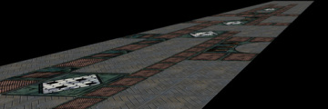
FIGURE 4.64 Games-eye view of the ground map.
You can use this technique to test your building sketches as well. Just adjust the ground plane image with the Distort tool to match the direction of the diametric grid (FIGURE 4.65).
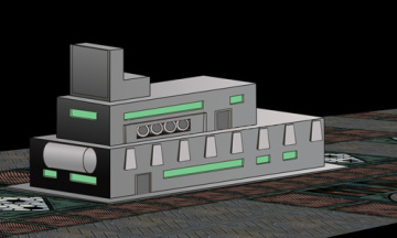
FIGURE 4.65 Building and grid in game view.
)
)
)
)
)
)
)
)
)
)