- Enhancing the IK Limb Controls
- Upgrading the Legs and Feet
- Creating Advanced Head and Torso Controls
This chapter is from the book
This chapter is from the book
This chapter is from the book
Creating Advanced Head and Torso Controls
This section covers the rest of the advanced controls, including skeleton controls for the head, face, and torso. Important new techniques will be shown in the interface, such as using spline IK for the backbone controls. At the end of the section advanced scripts for the main controls are explained in detail.
Upgrading the Head and Face Rig
In the basic rig only two skeletons were used for simple head controls: the main head skeleton and the jaw skeleton that was child to it. If you did a test bind of the basic rig and rotated the jaw joint, you would have noticed that the whole face collapsed in an unnatural way. If your head rig is too simple with too few joints, Maya is forced to guess at how to assign the weighting of the points. It will assign percentages of influence to the closest joint in 3D space. Because the jaw joint is close to many of the face points, Maya will automatically assign the joint too much influence, causing the face to collapse when the jaw is moved (see FIGURE 4.20).
)
Figure 4.20 Binding just the head and jaw joints on the basic rig makes the whole face collapse when the jaw is rotated, and requires extensive manual weighting to improve the deformation.
Adding Skeletons to the Face
To improve the face deformations without a lot of tedious manual weighting of points, it is best to add skeletons to all the main areas of the face, and then parent them under either the head or jaw joints. This will more clearly tell Maya how to weight the points on the face, and will reduce the amount of manual weighting required after binding. The best way to approach adding these skeletons is to define the main bone structures of the face, and examine how the muscles flex. Look at a good anatomy and physiology book to see how the muscles are structured on the face.
To add some face skeletons to the nose and jaw:
- Start by drawing skeletons that contour the main features of the face, holding down the V key as you draw to snap directly to points on the polygon skull and jaw bones. The purpose for adding these skeletons is to define what parts of the face should move with the head, and what should move with the jaw. Although you could snap directly to the skin model if it is available, to build or script a generic rig that will fit most biped characters, use the polygon bones for joint placement.
- Add skeletons to improve face deformations. Here are two examples, out of many possibilities:
- To keep the nose points from being assigned to the jaw joint, draw a new skeleton in the nose area from between the eyes to above the mouth, and parent it under the head joint. Name the joints ctNoseRoot, and so on.
- To ensure that points in the jaw area move with the jaw, and not the head, draw a skeleton around the contour of the left jaw edge from below the left ear to the center of the jaw (see FIGURE 4.21). Name the joints lfJawRoot, and so on. Mirror the skeleton to the right side, and parent both skeletons under the center jaw joint.
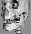
Figure 4.21 Snap joints to points on the polygon bones to contour the bony parts of the face and define the weighting, and then parent the new skeletons under the main jaw and skull joints.
)
Creating Muscle-Flexing with Skeletons
Other than adding static skeletons to improve weighting to the head and jaw, you can add skeletons to create muscle movements on the face as well. For instance, muscles on the forehead flex upward and downward to raise and lower the eyebrows. You can simulate this basic motion by adding three two-joint skeletons on the left, middle, and right sides of the forehead.
To add some face skeletons to the forehead that will flex the eyebrow muscles:
- Draw the left eyebrow skeleton over the left eye, from a point on top of the forehead area of the skull bone to a point somewhere around the middle of the left brow area. Name the joints lfBrowRoot, and so on. Mirror this skeleton to the right side, and then draw another skeleton down the middle of the forehead between the eyebrows (see FIGURE 4.22). Name the center joints ctBrowsRoot, and so on.
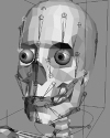
Figure 4.22 Create simple face controls by drawing skeletons in the direction that the muscles flex, such as on the forehead to create eyebrow controls.
Group all three skeletons together, and parent the group node under the head joint (double-group to keep bones from being displayed between the parented skeletons).
Just these three skeletons will let you shape the forehead to create simple brow movements by scaling them in their X axis. These movements can facilitate the creation of facial expressions such as sad, happy, and surprise. Most current facial rigs are a combination of joint transforms, which this chapter covers, and blend shapes, which will be covered in the next chapter.
)
Rotating Joints Around Facial Features
One reason joints are often used for face controls is that they rotate on arcs, while other methods like blend shapes morph in straight lines from shape to shape. On a basic blend shape without any in-between shapes, this movement could lead to unnatural deformations or intersections of surfaces in the middle of the morph. Joint controls can sometimes bypass this problem on the curved surfaces of the face. For instance, a good place on the face to incorporate the rotation of joints is in opening and closing the eyes.
To add some skeletons to open and close the eyes:
- Draw a two-joint skeleton from the center of the eyeball to the middle of the top eyelid. Name the joints lfEyeLidRoot, and so on. Since the eyeball is round, the skeleton will rotate on the correct arc to close the eye without intersecting the eye surface (see FIGURE 4.23). Be aware that points on the lower and side corners of the eye will be assigned to the top eyelid joints if you don't also add other skeletons to these areas.
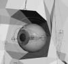
Figure 4.23 Using the natural arcs produced by rotating joints can create good eyelid controls for opening and closing the eyes.
Experiment with adding other face skeletons, such as a skeleton drawn from the sides of the cheek down to the corner of the mouth, which allows you to scale and rotate the joints to create a smile or grimace expression. Be aware that some manual weighting of the points will still be required when binding, especially to smooth out the deformations on the skin.
Once you've created and parented the skeletons to the rig hierarchy, add custom channels to the head icon to drive the joints using SDKs. In some cases, as on the eyebrow joints, drive the scaling in X to raise and lower the brows; in other cases, like the eyelid joints, drive the rotations to open and close the eyes. Experiment with driving both directions on the driven channel, as this can produce unexpected, but sometimes useful, facial expressions.
)
Building an Advanced Torso Rig
Upgrading the torso involves adding new skeletons and controls to the backbone, chest, and waist. The backbone skeleton will incorporate a new type of IK solver called spline IK, which has properties of both FK and IK skeletons. After creating the advanced backbone, you will create additional FK skeletons in the chest and stomach, driven with SDKs and expressions. This section also implements some advanced connections to create automatic torso controls for breathing and moving the upper body with the feet.
Preparing to Add Spline IK to the Backbone
Upgrading the backbone will be the most involved setup you do on the biped rig because there are so many nodes and connections involved. The process involves drawing skeletons, adding spline IK, binding spine IK curves to icons, connecting and setting advanced attributes, and parenting all the nodes into the basic rig hierarchy so everything works together.
The main part of the new backbone controls involves using the Spline IK solver, which creates and assigns a curve to a skeleton, so that the shape of the skeleton tries to mimic the shape of the curve. To continuously follow the shape of the curve, the solver calculates how the joints should rotate as the points on the curve are moved. Deforming the curve allows you to bend the skeleton in multiple directions, much like an FK skeleton, only with the ease of IK by moving points instead of an IK handle. Actually, moving points manually is not that easy, but you will be shown how to make icons easily control the curve points instead. Lastly, spline IK does create an IK handle, but it is used only to set spline IK attributes, not to animate transforms.
To better fit the curvature of the polygon vertebrae, you must draw a new spine skeleton that has more joints than currently exist in the basic backbone rig. Such a skeleton will also better follow the points on a spline IK curve, and produce smoother deformations on the skin. Keep in mind, however, that you won't delete the original backbone skeleton, but use it as an FK control for the new spline IK backbone. These types of backbone controls were widely popularized by Jason Schliefer over the years at several Maya master classes held during SIGGRAPH conferences. Since then they have become an industry standard for creating a flexible backbone; as a result, any character rigging artist should know some variation of this type control.
Drawing the New Backbone Skeletons
You'll begin by creating two new FK backbone skeletons in the spine area from center hip to shoulder, and then a separate neck skeleton from center shoulder to head. Two main spine skeletons are necessary to move the neck independently from the back when you add the spline IK in the following section. In addition, several two-joint skeletons will be created in the hip, chest, and head areas to facilitate controlling the spline IK curves.
To create the new backbone skeletons:
In the Joint Tool options dialog box, make sure that standard IK is turned off. Using the polygon vertebrae as a guide, draw both of the new backbone skeletons in Side view, clicking between every other vertebra. This creates a Maya joint for every two polygon bones.
You should draw the back spine skeleton from the center pelvis to the base of the neck (vertebrae 0 to12). You should draw the neck spine skeleton from the base of the neck to the base of the skull (vertebrae 16 to 21). Make sure that the joints are positioned between the vertebrae (see FIGURE 4.24).
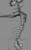
Figure 4.24 Draw the new backbone skeletons in Side view to center the joints between every two vertebra of the spine.
- Name the new back spine joints ctLowSpineRoot, ctLowSpine1, and so on, and name the neck spine joints ctUpSpineRoot, ctUpSpine1, and so on.
- Create a two-joint FK skeleton in the neck area from where the back spine skeleton ends at vertebra 12, up to where the neck spine skeleton starts at vertebra 16. Name the joints ctMidSpineRoot and ctMidSpineEnd. This skeleton will be used to bind the spline IK curves of the other two skeletons, which will partially control the shape of the curves.
- Create similar skeletons in the head and hip areas. Actually, these skeletons should be duplicates of the main center head and hip skeletons. Name the skeletons ctTopSpineRoot, ctBotSpineRoot, and so on. These skeletons will also be used to bind the spline IK curves.
- So that you can better see the effect of spline IK on the skeletons, re-parent all the polygon vertebrae under the appropriate joints. Because of how the skeletons were drawn, make sure you parent every two joints under the lower and upper skeleton joints. Parent vertebrae 12 to 15 under ctMidSpineRoot, and then make the pelvis and skull polygon bones children of the bottom and top skeletons.
- To prevent redundancy and weighting conflicts when binding, rename the original center hip, head, and backbone skeletons so they will not be bound. For instance, in the rigging scripts the joints are given a new suffix indicating they are now control joints (_ctrlRt and _ctrlJt).
)
Keep in mind that whenever you work on a character, you must choose how much resolution a particular control really needs. On the two main spine skeletons, for instance, too few Maya joints won't be flexible enough, while too many joints will be more difficult to bind and weight. Drawing a Maya joint for every polygon vertebrae produces too many joints. Creating a skeleton with a Maya joint for every two vertebrae produces a much more manageable skeleton, while still being flexible enough for a backbone. Though not an issue when creating a rig through code, working with fewer nodes speeds up the whole manual rigging process.
Adding Spline IK to the Skeletons
To add spline IK to the two main backbone skeletons:
- Choose Skeleton > IK Spline Handle Tool
 to activate the tool, and then click Reset Tool in the dialog box to use the default settings. Once the tool is activated, click Close to close the dialog box.
- In Perspective view, click the root joint followed by the end joint of the lower spine skeleton. You should see a new IK handle appear, and if you also look in the Hypergraph you will see a new curve has automatically been created (see FIGURE 4.25). Name the IK handle and curve ctLowSpineIk and ctLowSpineCurve.
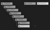
Figure 4.25 Adding spline IK to the spine skeleton creates an IK handle and curve that is used to rotate the joints.
- Select the spline IK curve in the Hypergraph, and press the F8 key to switch to component mode in Perspective view. The default IK spline handle settings, with a Number of Spans set to 1, creates a curve with four points. This is normally enough points for a human backbone, but if necessary you can increase the number of points, and thus the complexity of the curve, by increasing the span setting. Try moving some of the points to see how that flexes the skeleton by the solver rotating the joints.
- Repeat steps 1 to 3 on the upper spine skeleton in the neck area of the character, naming the spline IK nodes ctUpSpineIk and ctUpSpineCurve.
)
Do not be alarmed if you see a pink warning appear in the feedback field when you add the spline IK to the skeletons. This occurs because the spline IK handle is automatically selected, and you are never supposed to transform it like a standard IK handle. Maya is just indicating that spline IK should be controlled only by transforming the curve components. You'll learn how to do that in the next section
Creating the Spine Icon Controls
Since manually moving points on a curve is tedious, it is best to indirectly control the shape of the curve through icons. In the past, this was often done by creating clusters on the points and parenting the clusters under different icons. Instead, the technique shown here smooth-binds the spline IK curves to the two-joint skeletons created at the bottom, middle, and top of the spine.
- Bind the lower spline IK curve by Shift-selecting the root joints of the bottom and middle skeletons followed by the curve, and choose Skin > Bind Skin > Smooth Bind . In the dialog box, set bind to Joint Hierarchy using the Closest Distance method, set the Max Influences to 5, the Dropoff Rate to 4, and turn on all the other check boxes (see FIGURE 4.26). Then click Bind Skin to apply the settings.
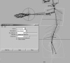
Figure 4.26 Binding the spline IK curve to joints parented under the icons allows easy manipulation of the points on the curve.
- Repeat the same binding process on the upper spine curve to the middle and top spine joints. After binding, rotating the joints should deform the curves and flex the spline IK skeletons.
- To make animating the spline IK easier, parent the two-joint skeletons under icons. You should parent the bottom and top skeletons under the hip and head icons. Since there is no icon for the middle skeleton, you should create a new box icon in the upper chest area.
- Run your box icon code, and transform and shape the icon to fit around the upper chest of the character, naming it ctSpine. Then parent the middle skeleton under the spine icon.
)
Rotating the icons will now flex the lower and upper spine skeletons, but the movement still doesn't look good because the rest of the hierarchy is not yet moving with the controls. Ignore this for now, as you have to complete a few more tasks before parenting all the nodes together.
Making the Lower Spine Stretchy
The curves stretch a little when you rotate the controls. This effect is not very obvious on the neck, but is more noticeable on the lower spine skeleton when the spine icon is moved and rotated. Too much movement causes the joints to become separated from the curve. For this reason, it is advisable to add some stretchy qualities to the skeleton joints. Of course, this is also a very useful technique for creating cartoon-style squash and stretch effects. However, even realistic character rigs look better with a little stretchiness added to their main backbone skeleton.
An easy way to add stretchiness to the lower spine is to write a math expression that uses the length of the curve to drive the scaling in local X axis of the spine joints. If you translate the joints in this direction, it effectively lengthens the skeleton. Translation propagates down the skeleton hierarchy differently than actually scaling the joints, but either technique can produce good stretching controls.
To add stretchiness to the lower spine joints:
- Create a node on the ctLowSpineCurve curve that contains a channel that registers its length. Select the curve, and run the following MEL command on the command line: arclen -ch 1;
- With the curve still selected, choose Window > Hypergraph: Connections to find a node named curveInfo1, and open it in the Attribute Editor. You will see an arcLength channel that registers the length of the curve (see FIGURE 4.27).
The 7.47 value displayed is the default length of the curve, and will be used in the expression to make the skeleton stretch. Keep in mind that this value will change for different-sized characters.
Figure 4.27 To add some stretch to the spine, you must first create a curveInfo1 node that has a channel that registers the length of the spline IK curve.
- Open the Expression Editor, and write an expression line for each joint in the lower spine skeleton, starting at the second joint. Here is what each line of the expression should look like:
ctLowSpine1.tx = 1.36 * ((curveInfo1.arcLength / 7.47) / topNode.sy);
The main part of this expression divides the current length channel value by the default value to determine if the curve has been stretched or compressed. This is multiplied by the joint's default translateX value, in this case 1.36, to drive the actual translation. Finally, dividing by the top node scaling in Y will keep the joints sized correctly in relation to the overall rig size. If the top node of the character is scaled to better fit the scene, for instance, the expression will compensate. - Copy and paste this expression line for each joint of the lower spine skeleton, only changing the joint name and the default X translation value. When you have finished, name the expression node stretchySpine, and click Create and Close.
- Move and rotate the spine icon to test the stretching on the joints of the skeleton. You should see the Maya skeleton stretch while every two polygon bones move with the joints. When the skin is bound, this movement will produce a smooth stretch.
)
Setting the Advanced Spline IK Twist Attributes
Currently, if you rotate the icons in Y, the spine skeleton won't rotate in its local X axis to twist the backbone. This is because spline IK twisting is not controlled by the points on the curve, but instead by a special attribute on the IK solver. In the past, it was common to drive the twist-and-roll channels on the handle to control twisting. Now Maya has an even easier option available on the IK handle, called the advanced twist attributes.
To set advanced spline IK twist attributes:
- In the Hypergraph, right-click the ctLowSpineIk IK handle to open the handle in the Attribute Editor, and click the IK Solver Attributes section to display the disabled Advanced Twist Controls.
- Turn on the Enable Twist Controls option and set these Advanced Twist controls (see FIGURE 4.28):
- Since you are using icons to twist the skeletons, set the World Up Type to Object Rotation Up (Start/End).
- Then set negative Z as the Up Axis and Vector in the next three options. This relates to the X orientation of the skeleton joints.
- Most importantly, type the full name of the hips icon into the first World Up Object field, and type the spine icon name in the second World Up Object field.
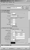
Figure 4.28 Spline IK curves won't twist unless you drive special attributes on the IK handle. You can easily do this by setting the advanced twist attributes in the Attribute Editor.
- Click Close to close the Attribute Editor, and repeat steps 1 through 2 on the upper spine IK handle.
)
This gives you all the nodes required to put together the hierarchy for the advanced backbone and finalize the torso rig.
Completing the Advanced Torso Rig
To connect all the advanced backbone nodes into the basic hierarchy:
- All the parts of the rig that used to move with the original backbone skeletons, such as the head and arms, should now move with the spline IK skeletons. The easiest way to do this is to re-parent the ctBackPad0 group node under the end joint of the new lower spine skeleton.
- To make the original FK backbone joints control the new spline IK, simply parent the spine icon under the ctBack2 joint. Since you are parenting the icon under a joint, insert group node pads between these controls to make sure that the spine icon generates world values when rotating.
- Rotate the original backbone joints to see if they move the spine icon, which in turn should move the spline IK skeletons. This setup gives you two levels of controls for manipulating the backbone. You should streamline the advanced backbone controls by adding custom channels on the icon; these channels will drive the FK rotation of the backbone joints using SDKs (see FIGURE 4.29).
Figure 4.29 Parent the new spine icon under the original FK backbone joints to create two levels of backbone controls.
Parent all other new spline IK nodes under the DoNotMove node at the top of the rig hierarchy. Since you are already controlling the new skeletons through the spline IK curves, it is not necessary to have them also move with parent transformations; that latter could move the nodes twice as far as they should move, called a double transform.
In addition to creating spline IK spine controls, upgrading the torso should also involve adding skeletons to the chest, ribs, and stomach to improve deformations on the skin when the backbone bends (see FIGURE 4.30). Draw the skeletons in the same way as done on the advanced face controls, and parent them to the closest spline IK backbone joints.
Figure 4.30 Add and drive skeletons in the chest, ribs, and torso to improve deformations, and to create muscle and skin effects.
)
)