- Introduction
- Using Isometric Snap
- Switching Isometric Planes
- Using COPY and Other Edit Commands
- Drawing Isometric Circles with ELLIPSE
- Drawing Text Aligned with Isometric Planes
- Drawing Ellipses in Orthographic Views
- Saving and Restoring Displays with VIEW
- Chapter Summary
- Chapter Test Questions
- Chapter Drawing Projects
This chapter is from the book
This chapter is from the book
This chapter is from the book
Using COPY and Other Edit Commands
Most commands work in the isometric planes just as they do in standard orthographic views. In this exercise, we construct an isometric view of a bracket using the LINE and COPY commands. Then, we draw angled corners using CHAMFER. In the next task, we draw a hole in the bracket with ELLIPSE, COPY, and TRIM.
✓ Clear your screen of boxes and check to see that Ortho mode is on.
✓ Switch to the left isoplane.
✓ Draw the L-shaped object shown in Figure 11-7.
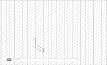
Figure 11-7 Drawing an L shape
Notice that this is drawn in the left isoplane and that it is 1.00 unit wide.
✓ Next, we copy this object 4.00 units back to the right to create the back surface of the bracket.
✓ Pick the Copy tool from the ribbon.
✓ Select all the lines in the L.
✓ Right-click to end object selection.
✓ Pick a base point at the inside corner of the L.
It is a good exercise to keep Ortho on, switch planes, and move the object around in each plane. You can move in two directions in each isoplane. To move the object back to the right, as shown in Figure 11-8, you must be in either the top or the right isoplane.
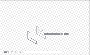
Figure 11-8 Copying the L shape
✓ Switch to the top or right isoplane and pick a second point of displacement 4.00 units back to the right, as shown in Figure 11-8.
✓ Press <Enter> to exit COPY.
✓ Enter the LINE command and draw the connecting lines in the right plane, as shown in Figure 11-9.
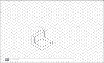
Figure 11-9 Drawing connecting lines
)
)
)
Creating Chamfers in an Isometric View
Keep in mind that inclined edges in an isometric view do not show true lengths. Edges of inclined planes must be drawn between endpoints located along paths that are vertical or horizontal in one of the three drawing planes. In our exercise, we create inclined edges by using the CHAMFER command to cut the corners of the bracket. This is no different from using CHAMFER in orthographic views.
✓ Pick the Chamfer tool from the Fillet drop-down list on the ribbon.
✓ Right-click and select Distance from the shortcut menu.
AutoCAD prompts for a first chamfer distance.
✓ Type 1 <Enter>.
✓ Press <Enter> to accept 1.00 as the second chamfer distance.
✓ Pick two edges of the bracket to create a chamfer, as shown in Figure 11-10.
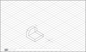
Figure 11-10 Chamfering corners
✓ Repeat CHAMFER.
✓ Chamfer the other three corners so that your drawing resembles Figure 11-10.
✓ To complete the bracket, enter the LINE command and draw lines between the new chamfer endpoints.
✓ Finally, erase the two unseen lines on the back surface, and the two corner lines left “in space” from the creation of the chamfer, to produce Figure 11-11.
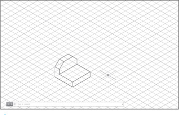
Figure 11-11 Drawing lines between endpoints
)
)