This chapter is from the book
This chapter is from the book
This chapter is from the book
4.7 Tutorials
Tutorial 4–1 Create Sweep Features
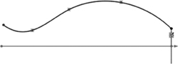
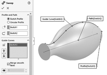
A sweep feature requires, at minimum, a profile (cross section) to sweep and a path (curve) to sweep along. You can use a guide curve to control the sweep further. If you do not use a guide curve, the sweep cross section stays constant.
Sweep operations may fail for different reasons. Figure 4.10 shows three error messages. As a general rule, the sweep path and guide must intersect the cross-section plane, and the cross section must not intersect itself as it traverses the path and/or the guide curve.
)
Figure 4.10 Some possible sweep operation errors
Create the sweep features shown in Figure 4.11. All dimensions are in inches.
)
Figure 4.11 Sweep features
No-guide-curve sweep (Figure 4.11A) modeling steps:
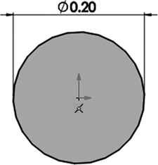
Step 1: Create Sketch1-Profile: File > New > Part > OK > Front Plane > Circle on Sketch tab > click origin and sketch circle and dimension as shown > exit sketch > File > Save As > tutorial4.1A > Save.
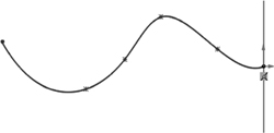
Step 2: Create Sketch2-Path: Right Plane > Spline on Sketch tab > sketch spline as shown (press Esc after last point is clicked to exit Spline); make sure spline snaps to origin > exit sketch.
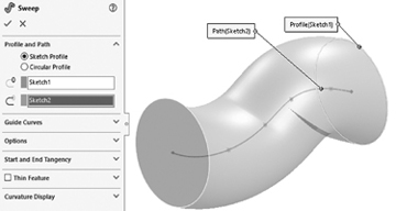
Step 3: Create Sweep1 feature: Sweep Boss/Base on Features tab > select circle sketch as Profile, as shown to the right > select spline sketch as Path, as shown to the right > ✓.
With-guide-curve sweep (Figure 4.11B) modeling steps:
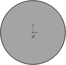
Step 1: Create Sketch1-Profile: File > New > Part > OK > Front Plane > Circle on Sketch tab > click origin and sketch circle as shown > exit sketch > File > Save As > tutorial4.1B > Save.
Step 2: Create Sketch2-Path: Top Plane > Line on Sketch tab > sketch line as shown (to the right) from origin > exit sketch.
Step 3: Create Sketch3-Guide: Right Plane > Spline on Sketch tab > sketch spline as shown (press Esc after last point is clicked to exit Spline); select spline endpoint near circle sketch > Ctrl + select circle sketch > Make Pierce > exit sketch.
Step 4: Create Sweep feature: Sweep Boss/Base on Features tab > select circle sketch as Profile, as shown > select Step 2 spline sketch as Path > select Step 3 spline sketch as Guide > ✓.
Tutorial 4–2 Create Loft Features
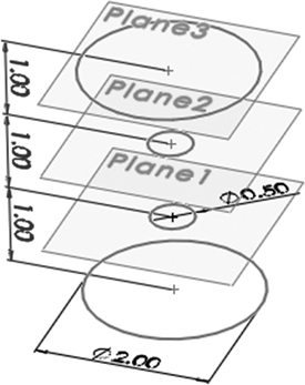
Create the wine glass shown in Figure 4.12. All dimensions are in inches. We introduce the concept of Convert Entities on the Sketch tab in this tutorial. You copy one circle in one sketch to another sketch. This concept enables you to copy entities from one sketch to another. While you could easily create a new circle and dimension it, using the Convert Entities method is faster (as there is no need to sketch a circle and dimension it). SolidWorks creates an On Edge relation between the two circles and shows a small green cube on the copied entity to indicate the relation. When you click the copied circle while editing the sketch, SolidWorks displays the On Edge relation in the relations pane to the left of the screen.
)
Figure 4.12 Loft feature
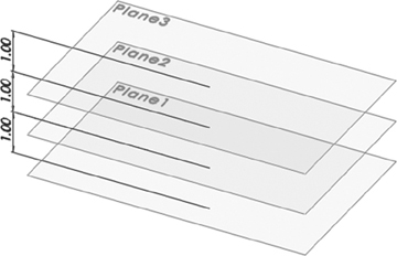
Step 1: Create Plane1–Plane3: File > New > Part > OK > Reference Geometry on Features tab > Plane > expand feature tree and select Top Plane > enter 1.0 for Offset Distance > ✓ > repeat for Plane2 and Plane3 but select the previously created plane > File > Save As > tutorial4.2 > Save.
Step 2: Create Sketch1–Sketch4: Top Plane > Circle on Sketch tab > click origin and drag to sketch and dimension a 2.0-inch diameter circle > exit sketch > select Plane1 as sketch plane and create a 0.5-inch diameter circle > exit sketch > select Plane2 as sketch plane > Sketch on Sketch tab > Convert Entities on Sketch tab > click circle on Plane1 > ✓ > ✓ > exit sketch > select Plane3 as sketch plane > Sketch on Sketch tab > Convert Entities on Sketch tab > click circle on Top Plane > ✓ > ✓> exit sketch.
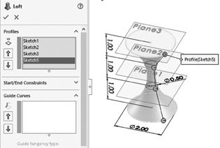
Step 3: Create Loft-Base feature: Lofted Boss/Base on Features tab > select Sketch1–Sketch4 > ✓.
Step 4: Create Plane4–Plane6: Reference Geometry on Features tab > Plane > expand feature tree and select Plane3 > enter 1.0 for distance > ✓ > repeat for Plane5 and Plane6 but select the previously created plane.
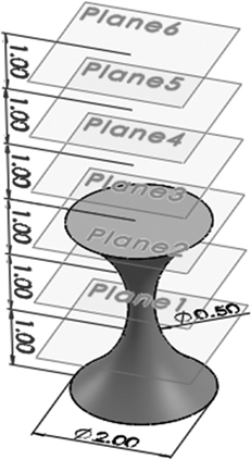
Step 5: Create Sketch5–Sketch7: Select Plane4 as Sketch Plane > Circle on Sketch tab > click origin and drag to sketch and dimension a 3.0-inch diameter circle > exit sketch > select Plane5 as Sketch Plane > Sketch on Sketch tab > Convert Entities on Sketch tab > click Sketch5 (just created) > ✓ > ✓> exit sketch > select Plane6 as sketch plane > Sketch on Sketch tab > Convert Entities on Sketch tab > click circle on Plane3 > ✓ > ✓> exit sketch.
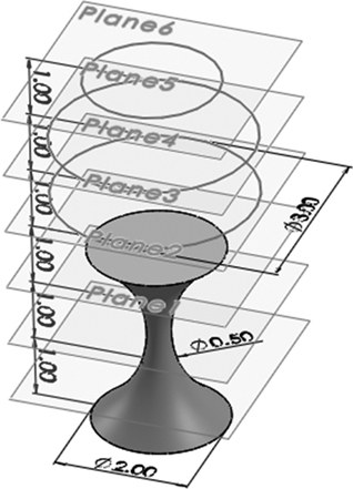
Step 6: Create Loft-Thin1-Top feature: Lofted Boss/Base on Features tab > select the circle of Sketch4 and then select Sketch5–Sketch7 > check Thin Feature box > enter 0.1 for thickness (T1) > if needed, click direction box to toggle direction of thickness to the inside > ✓.
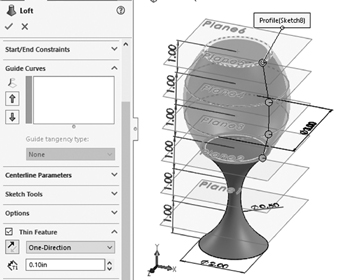
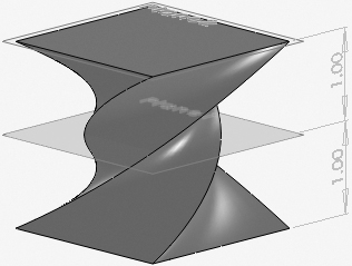
Note: Make sure you select the circle and sketches in a way so that the interpolation points (green circles shown here) line up; otherwise, you twist the loft.
Note: The thickness of the thin feature has a direction: inside or outside the profile. Reverse the direction of the double arrows shown to toggle.
Tutorial 4–3 Use the Hole Wizard
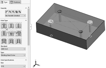
The hole wizard provides two advantages. First, it helps create standard hole sizes and types so that off-the-shelf bolts will fit perfectly in the holes. Second, it greatly speeds up the process of creating these holes. This tutorial shows how to create sample holes: counterbore, countersink, and tapped holes. Figure 4.13 shows these holes. You create an extrusion and add holes to it. You also create Sketch2 on the top face of the Block feature with a center rectangle (construction rectangle) that you use to place holes at its corners.
)
Figure 4.13 Wizard holes
Step 1: Create Sketch1 and Block feature: File > New > Part > OK > Top Plane > Extruded Boss/Base on Features tab > Center Rectangle on Sketch tab > click origin and sketch and dimension rectangle as shown > exit sketch > enter 1 for D1 > reverse extrusion direction > File > Save As > tutorial4.3 > Save.
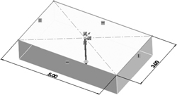
Step 2: Create Sketch2: Top face of Block > Center Rectangle on Sketch tab > click origin and sketch a 3.0 × 1.5 rectangle, as shown in Figure 4.13 > click For Construction box > exit sketch.
Step 3: Create two diagonal countersink hole features (CSK... node in feature tree): Hole Wizard on Features tab > select Countersink under Hole Type (hover over types until you read it) > select #8 for Size under Hole Specifications > Positions tab > click top face of Block and then click two corners of construction rectangles as shown > ✓.
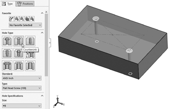
Step 4: Create two diagonal counterbore hole features (CBORE... node in feature tree): Hole Wizard on Features tab > select Counterbore under Hole Type (hover over types until you read it) > select #10 for Size under Hole Specifications > Positions tab > click top face of Block and then click two other corners of construction rectangles as shown > ✓.
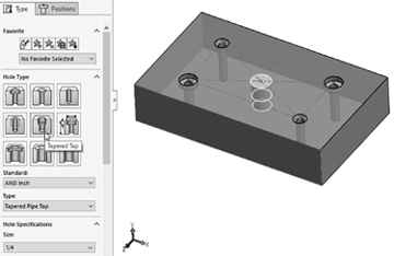
Step 5: Create Tapped Hole1 feature: Hole Wizard on Features tab > select Tapered Tap (hover over types until you read it) > select 1/4 for Size under Hole Specifications > Positions tab > click top face of Block and then click rectangle center as shown > ✓.
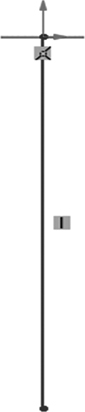
Tutorial 4–4 Create Compression Spring
Figure 4.14 shows the constant length compression spring you create in this tutorial.
)
Figure 4.14 Compression spring
Step 1: Create Sketch1 and Helix/Spiral1 curve: File > New > Part > OK > Top Plane > Circle on Sketch tab > click origin and sketch and dimension circle with 1.0-inch diameter > exit sketch > Insert (menu) > Curve > Helix/Spiral > select the circle just sketched > Height and Revolution from Defined By dropdown shown > Constant Pitch > enter 2.0 for Height, 20 for Revolutions, and 90 for Start Angle, as shown > ✓ > File > Save As > tutorial4.4 > Save.

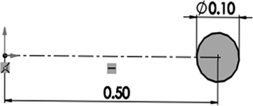
Step 2: Create Sketch2: Front Plane > Circle on Sketch tab > sketch and dimension circle as shown (align center with X-axis as shown) > exit sketch.
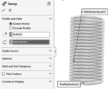
Step 3: Create Sweep1 feature (spring): Swept Boss/Base on Features tab > select Sketch2 as Profile > select Helix/Spiral1 as Path > ✓.
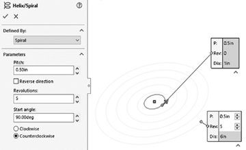
Tutorial 4–5 Create Spiral
Figure 4.15 shows the spiral spring you create in this tutorial.
)
Figure 4.15 Spiral spring
Step 1: Create Sketch1 and Helix/Spiral curve: File > New > Part > OK > Top Plane > Circle on Sketch tab > click origin and sketch and dimension circle with 1.0-inch diameter > exit sketch > Insert (menu) > Curve > Helix/Spiral > select the circle just created > Spiral from Defined By dropdown shown > enter 0.5 for Pitch and 5 for Revolutions, as shown > Start Angle of 90 and select Counterclockwise > ✓ > File > Save As > tutorial4.5 > Save.
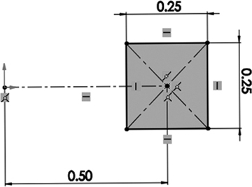
Step 2: Create Sketch2: Front Plane > Center Rectangle on Sketch tab > sketch and dimension rectangle as shown (align center with X-axis as shown) > exit sketch.
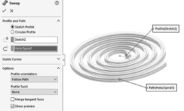
Step 3: Create Sweep feature (spiral): Swept Boss/Base on Features tab > select Sketch2 as Profile > select Helix/Spiral as Path > select Show Preview under Options > ✓.
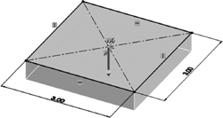
Tutorial 4–6 Create Features
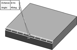
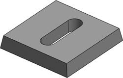
This tutorial covers the creation of these features: chamfer, fillet, slot, shell, draft, and rib. All dimensions are in inches. Consider these useful observations:
Make sure to pay attention to the visual clues shown in the left pane while creating these features.
For example, the box symbol under Chamfer parameters indicates that you can chamfer a face, an edge, or a vertex (corner point). As you would expect, chamfering a face chamfers all its edges. Chamfering a corner chamfers the three edges that meet there.
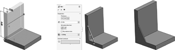
A rib requires a profile sketch (e.g., a line or stepwise line) and a thickness.
Step 1: Create Sketch1 and Block feature: File > New > Part > OK > Top Plane > Extruded Boss/Base on Features tab > Center Rectangle on Sketch tab > click origin and sketch and dimension as shown > exit sketch > reverse extrusion direction > enter 0.5 for D1 > ✓ > File > Save As > tutorial4.6 > Save.
Step 2: Chamfer an edge of Block feature: Fillet dropdown on Features tab > Chamfer > select Angle Distance chamfer > select Block edge shown > use 0.1 for Distance and 45 degrees for Angle > ✓.
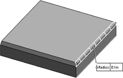
Step 3: Fillet an edge of Block feature: Fillet on Features tab > select Constant Size Fillet > select Block edge shown > use 0.1 for Radius > ✓.
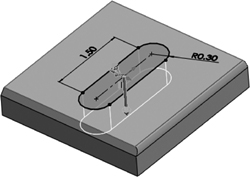
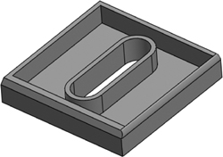
Step 4: Create a straight slot in Block feature: Select Block top face as a sketch plane > Extruded Cut on Features tab > Straight Slot on Sketch tab > sketch and dimension slot as shown > make origin and slot midpoint Coincident > exit sketch > Through All > ✓.
Step 5: Shell Block feature: Shell on Features tab > select top face of Block > enter 0.1 for D1 > ✓.
Step 6: Draft Block feature: Suppress the chamfer, fillet, and shell features > Draft on Features tab > enter 10 degrees for Draft Angle > select top face of Block as Neutral Plane > select Block four side faces to draft > ✓.
Step 7: Create a rib feature: Suppress the slot and draft features > select front face of Block > Extruded Boss/Base on Features tab > Rectangle on Sketch tab > sketch and dimension rectangle as shown below > exit sketch > reverse extrusion direction > enter 3.0 for D1 > ✓ > Front Plane > Rib on Features tab > Line on Sketch tab > sketch a line using the midpoints of the two edges as shown below > exit sketch > enter 0.5 for rib thickness (T1) > select Second Side for Thickness > Parallel to Sketch for Extrusion Direction > ✓.
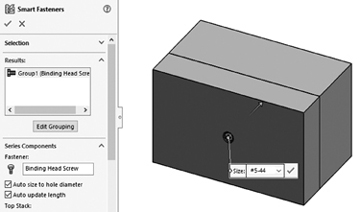
Tutorial 4–7 Use the Smart Fasteners Wizard
You use the Smart Fasteners wizard to insert the correct fastener based on the hole you select. It is a form of automation using off-the-shelf components. SolidWorks has its own standard library of fasteners. You can only use the wizard at the assembly level. You need to activate the wizard in order for the Smart Fasteners icon on the Assembly tab to work. If you click the icon before activation, you get this error: Smart Fasteners requires SolidWorks Toolbox, which is not present.
In this tutorial, you create an assembly of a block and plate. You create a counterbore hole in the plate and a blind hole in the block, assemble them, and fasten them together with a smart fastener. Figure 4.16 shows the assembly and its tree. All dimensions are in inches.
)
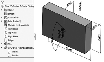
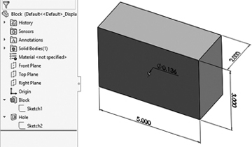
Figure 4.16 Assembly using smart fastener
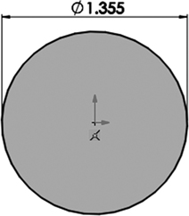
Step 1: Create Plate feature: File > New > Part > OK > Front Plane > Extruded Boss/Base on Features tab > Center Rectangle on Sketch tab > click origin and sketch and dimension rectangle as shown > exit sketch > enter 1 for D1 > reverse extrusion direction > ✓ > Hole Wizard on Features tab > select Counterbore under Hole Type (hover over each hole type until you read the correct type) > ANSI inch for Standard > binding head screw for Type > select #5 for Size under Hole Specifications > Positions tab > click front face of Plate and then click origin > ✓ > File > Save As > Plate > Save.
Note: The diameter of the counterbore hole shown below corresponds to #5 size. You need it to create the corresponding hole in the block in Step 2.
Step 2: Create Block feature: File > New > Part > OK > Front Plane > Extruded Boss/Base on Features tab > Center Rectangle on Sketch tab > click origin and sketch and dimension rectangle as shown > exit sketch > enter 2 for D1 > reverse extrusion direction > ✓ > front face of Block > Extruded Cut on Features tab > Circle on Sketch tab > click origin and sketch and dimension as shown > exit sketch > enter 1 for D1 > ✓ > File > Save As > Block > Save.
Step 3: Create assembly: File > New > Assembly > OK > Browse > locate Block and Plate parts > select Block + Ctrl + Plate > Open > click ✓ to place Block instance in assembly origin > click anywhere in graphics pane to place Plate instance > Mate on Assembly tab > Coincident > select the corresponding top edges of Block and Plate > ✓ > select the corresponding right edges of Block and Plate > ✓ > ✓.
Step 4: Activate Smart Fasteners wizard: Tools > Add-Ins > SolidWorks Toolbox Library > OK. This adds the Toolbox menu to the menu bar to the right of the Tools menu. You may deactivate the Toolbox by using the same sequence but unchecking the Toolbox Browser from the Add-Ins window.
Step 5: Add a fastener: Smart Fasteners on Assembly tab > OK (to accept that it may take extra time) > expand feature tree > expand Plate instance tree node > select CBORE for #5 node > Add > ✓ > File > Save As > Tutorial4.7 > Save.
Tutorial 4–8 Create a Bolt
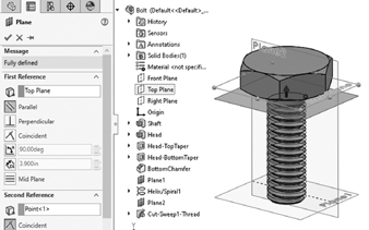
Bolts, like gears, are important and essential mechanical elements. While bolts are standard off-the-shelf components, this tutorial shows how to create the CAD model of one due to its learning value. Figure 4.17 shows the bolt and its feature tree. All dimensions are in inches.
)
Figure 4.17 A bolt
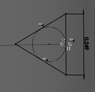
Step 1: Create Sketch1 and Shaft feature: File > New > Part > OK > Top Plane > Extruded Boss/Base on Features tab > Circle on Sketch tab > click origin and sketch and dimension as shown > exit sketch > enter 4 for D1 > reverse extrusion direction > ✓ > File > Save As > Bolt > Save.
Step 2: Create Sketch2 and Head feature: Select top face of Shaft feature > Extruded Boss/Base on Features tab > Polygon (hexagon icon) on Sketch tab > click origin and sketch and dimension as shown > apply vertical relation to one edge > exit sketch > enter 0.9 for D1 > ✓.
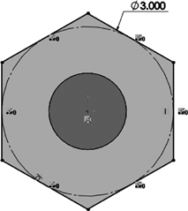
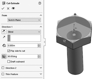
Step 3: Create Sketch3 and Head-TopTaper feature: Select top face of Head feature > Extruded Cut > Circle on Sketch tab > click origin and sketch (make circle tangent to hexagon sides) > exit sketch > enter 0.5 for D1 > click checkbox as shown > enter 60 for draft angle > ✓ > repeat to create Head-BottomTaper to chamfer the bottom of the head.
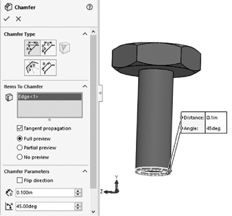
Step 4: Create BottomChamfer feature: Fillet dropdown on Features tab > Chamfer > select bottom edge of Shaft feature > enter 0.1 for D > enter 45 for A > ✓.
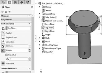
Step 5: Create Plane1: Reference Geometry on Features tab > Plane > expand feature tree > select Top Plane > enter 3.9 for D1 > click Flip offset checkbox > ✓.
Note: You use a distance of 3.9 for Plane1, not 4.0, because the chamfer is 0.1 high.
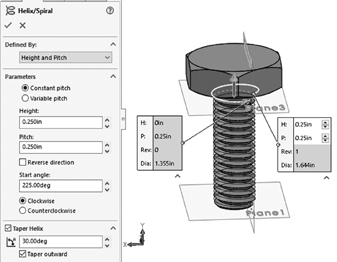
Step 6: Create Sketch5 and Helix/Spiral1: Select Plane1 > select Sketch on Sketch tab > Convert Entities on Sketch tab > expand feature tree > select Sketch1 > ✓ > exit Sketch > select Sketch5 > Insert > Curve > Helix/Spiral > select Height and Pitch > enter 3.5 for Height, 0.25 for Pitch, and 225 for Start angle > ✓.
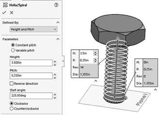
Note: The helix 3.5 height is arbitrary. That leaves 0.4 (out of 3.9). You use 0.25 for the other end thread helix and 0.15 underneath the bottom of bolt head as a length with no threads.
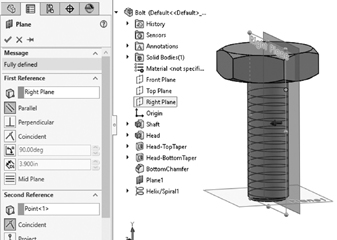
Step 7: Create Plane2: Reference Geometry on Features tab > Plane > expand feature tree > select Right Plane > select Parallel > click Second Reference box > select top endpoint of Helix/Spiral1 > ✓.
Step 8: Create Sketch6 and Cut-Sweep1-Thread feature: Select Plane2 > select Sketch Swept Cut on Features tab > Polygon (hexagon icon) on Sketch tab > 3 for Number of Sides > click near end of helix and sketch and dimension as shown with right side vertical and Helix/Spiral1 endpoint and right triangle edge midpoint coincident > exit sketch > Swept Cut on Features tab > select Sketch6 as Profile > select Helix/Spiral1 as Path > ✓.
Step 9: Create Plane3: Reference Geometry on Features tab > Plane > expand feature tree > select Top Plane > select Parallel > click Second Reference box > select top endpoint of Helix/Spiral1 > ✓.
Step 10: Create Sketch7 and Helix/Spiral2: Select Plane3 > select Sketch on Sketch tab Convert Entities on Sketch tab > expand feature tree > select Sketch1 > ✓ > exit sketch > select Sketch7 > Insert > Curve > Helix/Spiral > select Height and Pitch > enter 0.25 for Height > click Taper Helix checkbox > enter 30 for taper angle (A) > click Taper outward checkbox > ✓.
Step 11: Create Cut-Sweep2-EndThread feature: Swept Cut on Features tab > select Sketch6 as Profile > select Helix/Spiral2 as Path > ✓.