This chapter is from the book
This chapter is from the book
This chapter is from the book
Problems
What is a feature? Give two examples of features.
Why can an extruded cut or a revolved cut not be a base feature?
What is the required input needed to create a sweep? What is the optional input?
What is the required input needed to create a loft? What is the optional input?
Table 4.1 shows a rib feature. Which is the better way to create it: by using a rib or by using an extrusion? Explain your answer.
Table 4.1 shows a block that is shelled. Which is the better way to create it: by using shelling or by using extrusion cut? Explain your answer.
A spur gear has a pitch circle radius of 3 inches, a pressure angle of 14.5 degrees, and 20 teeth. Calculate all the parameters required to create the gear CAD model. Create the CAD model.
Same as Problem 7, but for a pitch circle radius of 100 mm, pressure angle of 14.5 degrees, and 30 teeth.
Create a macro to automate the creation of a donut revolve.
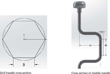
Create the brace drill handle shown in Figure 4.18. All dimensions are in millimeters.
Create the loft feature shown in Figure 4.19. Assume dimensions. Hint #1: This loft shows you the local and global influence of the guide curve. Hint #2: Use Guide curves influence types under the Guide Curves section shown on the left pane of the screen.
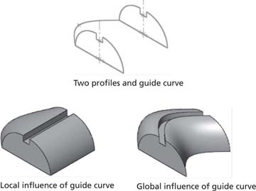
Figure 4.19 Influence of guide curve
Create the CAD model of the helical spring shown in Figure 4.20. All dimensions are in centimeters.
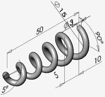
Figure 4.20 Helical spring
Create the CAD model of the 3D probe shown in Figure 4.21. All dimensions are in millimeters.
Create the CAD model of the football goal post shown in Figure 4.22. All dimensions are in inches. Hint: The dimensions of the post are per NFL specs: The post is 10 feet (120 in.) high, the crossbar is 18.5 feet (222 in.) wide from the inner edges of the uprights, and the uprights are 20 feet (240 in.) high. The diameter of the post tubes is arbitrary, so use 8 in. here.
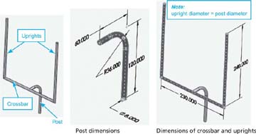
Figure 4.22 Football goal post
Create the CAD models shown in Figure 4.23. All dimensions are in inches.
Figure 4.23 CAD models
Create the CAD models shown in Figure 4.24. All dimensions are in inches.
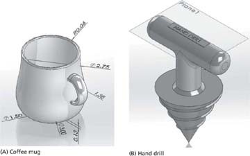
Figure 4.24 CAD models
Create the CAD models shown in Figure 4.25. All dimensions are in inches.
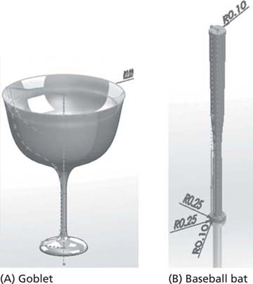
Figure 4.25 CAD models
Create the CAD models shown in Figure 4.26.
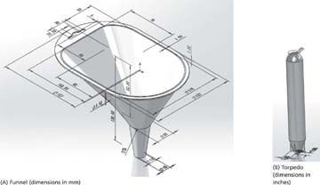
Figure 4.26 CAD models
Create the CAD models shown in Figure 4.27. All dimensions are in inches.
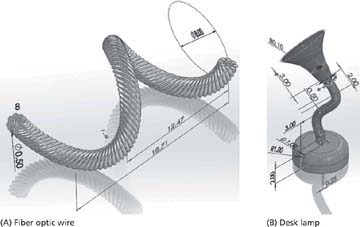
Figure 4.27 CAD models
Create the CAD models shown in Figure 4.28. All dimensions are in inches.
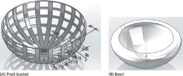
Figure 4.28 CAD models
Create the CAD models shown in Figure 4.29.
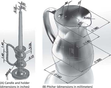
Figure 4.29 CAD models
Create the CAD models shown in Figure 4.30.
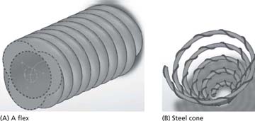
Figure 4.30 CAD models
Create the CAD models shown in Figure 4.31.
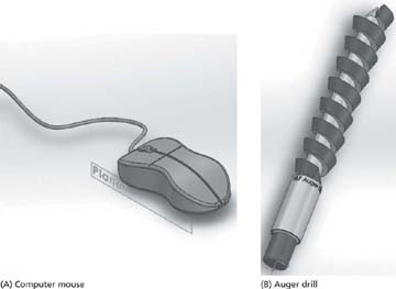
Figure 4.31 CAD models
)
)
)

)
)
)
)
)
)
)
)
)
)
)
)