- Chapter Objectives
- EXERCISE 3-1 Drawing a Rectangular Conference Room, Including Furniture
- Making a Drawing Template
- Polyline
- OFFSET
- EXPLODE
- ID Point
- TRIM
- Rectangle
- CHAMFER
- FILLET
- COPY and Osnap-Midpoint
- ROTATE
- POINT
- DIVIDE
- MEASURE
- OSNAP
- MIRROR
- Osnap Modes That Snap to Specific Drawing Features
- Running Osnap Modes
- Osnap Settings: Marker, Aperture, Magnet, Tooltip
- EXERCISE 3-2 Drawing a Rectangular Lecture Room, Including Furniture
- Making Solid Walls Using Polyline and Solid Hatch
- From
- BREAK
- Polyline Edit
- HATCH
- ARRAY
- ARRAYEDIT
- Distance
- Exercise 3-3 Drawing a Curved Conference Room, Including Furniture
- Polyline
- POLYGON
- Grips—Add Vertex
- Grips—Convert to Arc
- ARRAY
- Exercise 3-4 Drawing a Conference Room Using Polar Tracking
- Polar Tracking
- Polyline Edit
- Specifying Points with Tracking
- Drawing the Chairs around the Conference Table
- Completing the Conference Room
- Using Command Preview
- Choosing Selection Options
This chapter is from the book
This chapter is from the book
This chapter is from the book
ARRAY
Polar
The Polar option of the ARRAY command allows you to make multiple copies of an object in a circular array. You can specify a 360° Angle to fill to form a full circular array. You can specify an angle less than 360° to form a partial circular array. When you specify a positive angle, the array is rotated counterclockwise (+=ccw). When you specify a negative angle, the array is rotated clockwise (−=cw).
Polar: The option of the ARRAY command that allows you to make multiple copies of an object in a circular array.
POLAR ARRAY |
|
|---|---|
Ribbon/Panel |
Home/Modify
|
Modify Toolbar: |
|
Menu Bar: |
Modify/Array/Polar Array |
Type a Command: |
ARRAY |
Command Alias: |
AR |


AutoCAD constructs the array by determining the distance from the array’s center point to a point on the object selected. If more than one object is selected, the reference point is on the last item in the selection set.
Step 26. Use the POLAR ARRAY command to make a polar (circular) pattern of eight chairs (Figure 3-45), as described next:
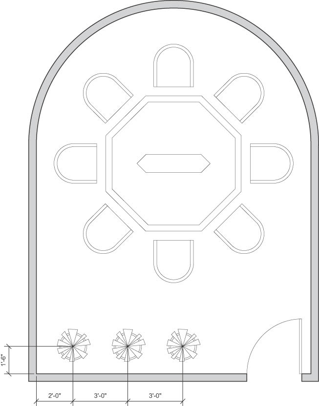
Figure 3-45 Array the chairs, draw the potted plant and copy it, and hatch the walls
Prompt
Response
Type a command:
Polar Array (or type ARRAYPOLAR <Enter>)
Select objects:
Click the first corner for a window to select the chair just drawn
Specify opposite corner:
Window the chair just drawn
Select objects:
<Enter>
Specify center point of array [or Base point Axis of rotation]:
Click the center point of the polygon using the Geometric Center (GCEN) object snap mode.
Select grip to edit array or [ASsociative Base point Items Angle between Fill angle ROWs Levels ROTate items eXit] <eXit>:
Type I<Enter>i
Enter number of items in array or [Expression] <6>:
Type 8<Enter>
Select grip to edit array or [ASsociative Base point Items Angle between Fill angle ROWs Levels ROTate items eXit]<eXit>:
<Enter>
Step 27. Use Zoom-Window to zoom in on the area of the conference room where the plants and planters are located (Figure 3-45).
Step 28. Use the CIRCLE command, 9″ radius, to draw the outside shape of one planter.
Step 29. Use the OFFSET command, offset distance 1″, offset to the inside of the planter, to give a thickness to the planter.
Step 30. Use the LINE command to draw multisegmented shapes (to show a plant) in the planter (Figure 3-45).
Step 31. Use the TRIM command to trim the lines of the pot beneath the plant leaves. Window the entire planter to select the cutting edges, and then select the lines to trim.
Step 32. Use the COPY command to draw the next two planters, as shown in Figure 3-45.
Step 33. Create the following new layer and set it as the current layer:
Layer name
Color
Linetype
Lineweight
a-wall-patt-gray
gray (253)
continuous
.004″ (.09 mm)
Step 34. Use the HATCH command to make the walls solid (Figure 3-45).
Step 35. Set layer a-anno-text current.
Step 36. Use the Single Line Text command (type DT <Enter>) to type your name, class number, and date, 6″ high in the upper-right corner.
Step 37. When you have completed Exercise 3-3 (Figure 3-46), save your work in at least two places.
Step 38. Print your drawing from the Model tab at a scale of 1/4″ = 1′-0″.
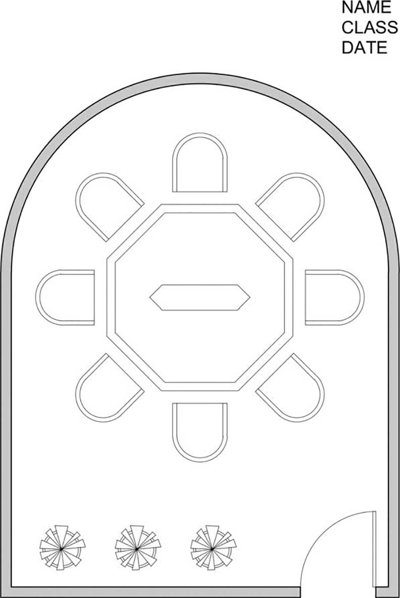
Figure 3-46 Exercise 3-3 complete
)
)