Geometry for Modeling and Design
- Objectives
- Overview
- Coordinates for 3D Cad Modeling
- Geometric Entities
- 4.1 Manually Bisecting a Line or Circular Arc
- 4.2 Drawing Tangents to Two Circles
- 4.3 Drawing an Arc Tangent to a Line or Arc and through a Point
- 4.4 Bisecting an Angle
- 4.5 Drawing a Line through a Point and Parallel to a Line
- 4.6 Drawing a Triangle with Sides Given
- 4.7 Drawing a Right Triangle with Hypotenuse and One Side Given
- 4.8 Laying Out an Angle
- 4.9 Drawing an Equilateral Triangle
- 4.10 Polygons
- 4.11 Drawing a Regular Pentagon
- 4.12 Drawing a Hexagon
- 4.13 Ellipses
- 4.14 Spline Curves
- 4.15 Geometric Relationships
- 4.16 Solid Primitives
- 4.17 Recognizing Symmetry
- 4.18 Extruded Forms
- 4.19 Revolved Forms
- 4.20 Irregular Surfaces
- 4.21 User Coordinate Systems
- 4.22 Transformations
- Key Words
- Chapter Summary
- Skills Summary
- Review Questions
- Chapter Exercises
In this sample chapter from Technical Drawing with Engineering Graphics, 16th Edition identify basic elements, select profiles, sketch symmetry, explore extrusion and revolution techniques, define Boolean operations, and work with CAD transformations.
Objectives
After studying the material in this chapter, you should be able to:
Identify and specify basic geometric elements and primitive shapes.
Select a 2D profile that best describes the shape of an object.
Identify mirrored shapes and sketch their lines of symmetry.
Identify shapes that can be formed by extrusion and sketch their cross sections.
Identify shapes that can be formed by revolution techniques and sketch their profiles.
Define Boolean operations.
Specify the Boolean operations to combine primitive shapes into a complex shape.
Work with Cartesian coordinates and user coordinate systems in a CAD system.
Identify the transformations common to CAD systems.

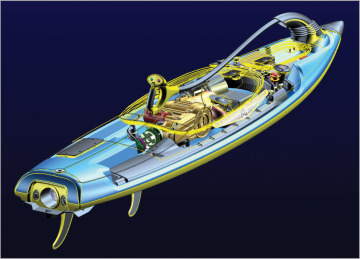
Many different geometric shapes were used to model this jetboard. The wireframe view of the top cover reveals several regular geometric shapes used to model the interior components. The graceful lines of the outer hull are defined by the irregular curves used to model it. (Courtesy of Leo Greene, www.e-Cognition.net.)
