- 7-1 Introduction
- 7-2 Terminology and Conventions-ANSI
- 7-3 Adding Dimensions to a Drawing
- 7-4 Drawing Scale
- 7-5 Units
- 7-6 Dimensioning Holes and Fillets
- 7-7 Dimensioning Counterbored and Countersunk Holes
- 7-8 Angular Dimensions
- 7-9 Ordinate Dimensions
- 7-10 Baseline Dimensions
- 7-11 Locating Dimensions
- 7-12 Fillets and Rounds
- 7-13 Rounded Shapes-Internal
- 7-14 Rounded Shapes-External
- 7-15 Irregular Surfaces
- 7-16 Polar Dimensions
- 7-17 Chamfers
- 7-18 Symbols and Abbreviations
- 7-19 Symmetrical and Centerline Symbols
- 7-20 Dimensioning to a Point
- 7-21 Dimensioning Section Views
- 7-22 Dimensioning Orthographic Views
- Chapter Projects
7-22 Dimensioning Orthographic Views
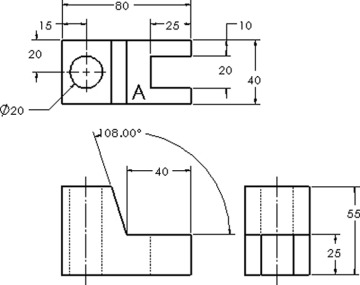
Dimensions should be added to orthographic views where the features appear in contour. Holes should be dimensioned in their circular views. Figure 7-70 shows three views of an object that has been dimensioned.
The hole dimensions are added to the top view, where the hole appears circular. The slot is also dimensioned in the top view because it appears in contour. The slanted surface is dimensioned in the front view.
The height of surface A is given in the side view rather than run along extension lines across the front view. The length of surface A is given in the front view. This is a contour view of the surface.
It is considered good practice to keep dimensions in groups. This makes it easier for the viewer to find dimensions.
Be careful not to double dimension a distance. A distance should be dimensioned only once. If a 30 dimension were added above the 25 dimension on the right-side view, it would be an error. The distance would be double dimensioned: once with the  dimension, and again with the 55 overall dimension. The
  dimensions are mathematically equal to the 55 overall dimension, but there is a distinct difference in how they affect the manufacturing tolerances. Double dimensions are explained more fully in Chapter 8.
Dimensions Using Centerlines
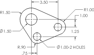
Figure 7-71 shows an object dimensioned from its centerline. This type of dimensioning is used when the distance between the holes relative to each other is critical.


