- 7-1 Introduction
- 7-2 Terminology and Conventions-ANSI
- 7-3 Adding Dimensions to a Drawing
- 7-4 Drawing Scale
- 7-5 Units
- 7-6 Dimensioning Holes and Fillets
- 7-7 Dimensioning Counterbored and Countersunk Holes
- 7-8 Angular Dimensions
- 7-9 Ordinate Dimensions
- 7-10 Baseline Dimensions
- 7-11 Locating Dimensions
- 7-12 Fillets and Rounds
- 7-13 Rounded Shapes-Internal
- 7-14 Rounded Shapes-External
- 7-15 Irregular Surfaces
- 7-16 Polar Dimensions
- 7-17 Chamfers
- 7-18 Symbols and Abbreviations
- 7-19 Symmetrical and Centerline Symbols
- 7-20 Dimensioning to a Point
- 7-21 Dimensioning Section Views
- 7-22 Dimensioning Orthographic Views
- Chapter Projects
7-6 Dimensioning Holes and Fillets
A blind hole is a hole that does not go completely through an object. It has a depth requirement. Figure 7-30 shows a  cube with a blind
  DEEP hole. It was created as follows.
Dimensioning a Blind Hole
1 Draw the block.
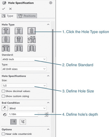
2 Click the Hole Wizard tool.
See Figure 7-30.
3 Click the Hole tool in the Hole Type box. Define the hole using the ANSI Inch standard with a Size of 1/2 and a Blind Hole Depth of 1.18in.
4 Click the Positions tab.
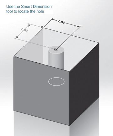
5 Locate the hole as shown.
The initial location is an approximation. Use the Smart Dimension tool to specify the exact location of the hole’s centerpoint.
6 Click the green OK check mark.
7 Save the drawing as Block, Blind.
8 Start a new Drawing document and create a front and a top orthographic view of the Block, Blind.
9 Add dimensions to the views.
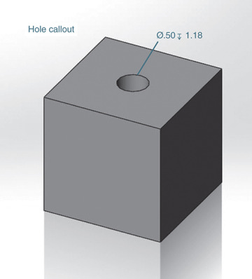
10 Click the Annotation tab and click the Hole Callout option.
11 Click the edge of the hole, move the cursor away from the hole, define a location for the hole callout, and click the mouse. The hole callout dimension will initially appear as a rectangular box.
Change the height of the text font if necessary.
12 Save the drawing.
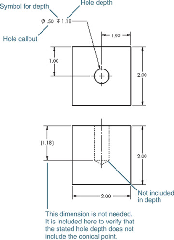
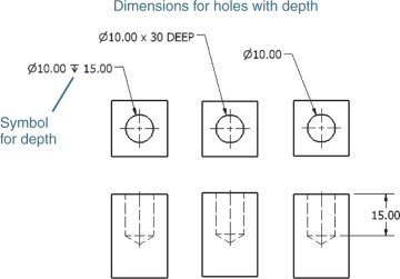
Note that the hole includes a conical point. Holes manufactured using twist drills will have conical points. The conical point is not included in the hole’s depth dimension. A special drill bit can be used to create a flat-bottomed hole.
Figure 7-31 shows three different methods that can be used to dimension a blind hole.
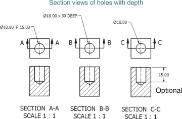
Figure 7-32 shows three methods of dimensioning holes in section views. The single line note version is the preferred method.
Dimensioning Hole Patterns
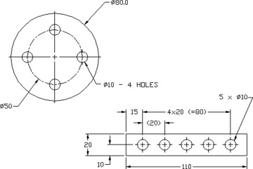
Figure 7-33 shows two different hole patterns dimensioned. The circular pattern includes the note  HOLES. This note serves to define all four holes within the object.
Figure 7-33 also shows a rectangular object that contains five holes of equal diameter, equally spaced from one another. The notation  specifies five holes of 10 diameter. The notation
  means four equal spaces of 20. The notation
  is a reference dimension and is included for convenience. Reference dimensions are explained in Chapter 9.
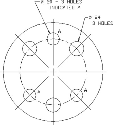
Figure 7-34 shows two additional methods for dimensioning repeating hole patterns. Figure 7-35 shows a circular hole pattern that includes two different hole diameters. The hole diameters are not noticeably different and could be confused. One group is defined by indicating letter A; the other is dimensioned in a normal manner.
