Dimensioning
- 7-1 Introduction
- 7-2 Terminology and Conventions-ANSI
- 7-3 Adding Dimensions to a Drawing
- 7-4 Drawing Scale
- 7-5 Units
- 7-6 Dimensioning Holes and Fillets
- 7-7 Dimensioning Counterbored and Countersunk Holes
- 7-8 Angular Dimensions
- 7-9 Ordinate Dimensions
- 7-10 Baseline Dimensions
- 7-11 Locating Dimensions
- 7-12 Fillets and Rounds
- 7-13 Rounded Shapes-Internal
- 7-14 Rounded Shapes-External
- 7-15 Irregular Surfaces
- 7-16 Polar Dimensions
- 7-17 Chamfers
- 7-18 Symbols and Abbreviations
- 7-19 Symmetrical and Centerline Symbols
- 7-20 Dimensioning to a Point
- 7-21 Dimensioning Section Views
- 7-22 Dimensioning Orthographic Views
- Chapter Projects
In this sample chapter from Engineering Design and Graphics with SolidWorks 2023, authors Jim Bethune and Nathan Brown delve into adding dimensions to SolidWorks drawings, differentiating between construction and defining dimensions with the Smart Dimension tool. Learn about ANSI Inch, Metric, and ISO systems, alongside key terminology, conventions, and dimensioning practices, including common errors to avoid. The chapter provides guidance on dimensioning various elements like holes, fillets, and complex shapes, ensuring clear and accurate working drawings through practical tips and tools like Autodimension.
7-1 Introduction
Dimensions are added to SolidWorks on Drawing documents. Dimensions will appear in Part documents, but these are construction dimensions. These sketch dimensions are used to create a part and are used when a sketch is edited. They may be modified as the part is being created using the Smart Dimension tool. They will not appear on the finished model or in Assembly documents.
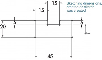
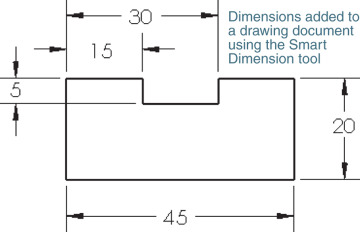
Figure 7-1 shows a dimensioned shape. The drawing on the left in Figure 7-1 shows the sketch dimensions that were used as the part was being created. The drawing on the right in Figure 7-1 shows dimensions that were created using the Smart Dimension tool in a Drawing document. These are defining dimensions and will appear on the working drawings. This chapter will show how to apply these types of dimensions.
SolidWorks has ANSI Inch and ANSI Metric dimensions available. Other dimensioning systems such as ISO also are available. This text is in compliance with ANSI standards.

